Showing posts with label Modelling and conversions.. Show all posts

Monday, 20 May 2024

The Haru-pa-kaut

From Wikipedia: Heru-pa-kaut – A mother goddess with a fish on her head.

When at Partizan yesterday, speaking to a few old friends (who I haven't seen for ages) about current projects, I mentioned the Heru-pa-kaut, the latest addition to my 'terrain pieces'. I thought I'd done a post about the Haru-pa-kaut but, looking back I find I haven't. What I did, for reasons I no longer remember, was to simply load up a bunch of photographs and add them to an old previously existing post - so it was probably missed by almost everyone.

Anyway, here she is: The Heru-Pa-Kaut, my first Nile paddle steamer for my adventures in Sudan.


This model basically follows a design I found on quindia studios blogspot. That model was made by extensively converting a plastic kit to make a model for 28mm gaming. When I first found this post my plan was to simply copy what he had done; then, I found out the model price; then, the Yorkshireman in me came out and I decided to go for something scratch built. The linked quindia studios post is definitely worth a visit - if only to show how much better some people are at modelling than I am - his model knocks the socks off mine. Thank you for your inspiring post, Quindia Studios.

Anyway, here is my version, made on the cheap. It's the first boat (outside the odd 1:600 galley) that I've ever made so everything was done on the fly and, outside of the basic design, it was very much an organic process from beginning to end and, until quite far in, I wasn't sure if it would come off.

What's the first thing I chose to make? The boiler. 

Why? Because, I figured, if I can make that I can probably make the rest. Turn around, touch the ground, spit....

The boiler is made from mounting card, thick paper, buttons and a couple of shields, more or less. The funnel is a plastic pen. The body of the boiler is thick paper shaped over internal mounting card ribs/fins. The ribs also serve to form the boilers legs/ and ends. Everything else is just applique work. Buttons were used because they are pre made perfect small discs, as are the shields. The riveted plates were a new discovery on my part: I cut pieces of thin card, placed them on a cork board and poked holes through the card with a thick pin - causing the card to burr on the reverse; then I put PVA glue into the holes to hold the burr in shape before gluing the plates onto the boiler, with burrs (rivets) outward. 

Next, of course was the wheel, shown next to the lower hull without it's sides.

Now, unfortunately I didn't take any photos of the wheel under construction (to be honest, I wasn't sure the first method would work and was concentrating so hard to make it work that it slipped my mind to). However, although a little time consuming, it proved to be a pretty straight forward way to do it. Here's how:

First, using a compass, I drew concentric circles on mounting card to form the hubs and rims for each side of the wheel. I needed four hubs and two rims. There are two hubs for each side of the paddle wheel, an inner and an outer, but only one rim for each. 

Whilst doing that, I did a copy of the hub and rim, as the wheel would look, on a separate piece of paper. This drawing of the wheel would be used as a bed on which the outer wheels could be constructed. I drew a line across the centre of this wheel then, using a compass, divided the wheel into sixteen equal segments - the spoke positions. Now, I did this without thinking because it's generally the method I use to equally divide up a circle but, looking at real paddle wheels, a lot seem to be twelve spoke so perhaps a protractor (and 30 degree segments) might be a better way. Anyway, I did what I did. Also, its on this piece of paper that you need to decide where the water line is and mark it on (you will use this to cut your rim and spokes at the water line), and draw an inner 'hole' on the hub around which your spokes will sit (the spokes cannot go to the very centre of the hub - because they have width, they won't fit).

After very carefully cutting out the mounting board hubs and rims with a very sharp 10A scalpel blade (I used a new blade for each rim), I took a hub and rim, laid them on the 'construction' sheet, which was pinned to a cork board, pinned them in place and cut the rim at the waterline. Then, I PVA glued the spokes into position using tweezers. Then I glued on the inner hub to secure the lot. When dry, I unpinned the now constructed side of the wheel and repeated the process for the other side of the wheel. 

After the wheel sides were done I glued the axle into place - this was made using a length of plastic pen. Now the exact width of the paddle wheel was known I cut out my mounting board paddles and glued them on. Afterwards, I was pleasantly surprised by the wheel's strength, and even more surprised at how good it looked - for a wheel made out of card, by me.

Two notes on the spokes: 
1. Spokes need to be accurately cut to length and need to be long enough to protrude beyond the rim to hold the paddles.
2. I made my spokes out of 'sealed' mounting card - sealing thin strips of card keeps them together and adds strength. To seal a strip of card I rub liberal amounts of PVA up and down it between my fingers. Then I hang the strip dry. The photographed strips are not spokes, these ones are thicker, wider planks that were used later, but the sealing process was the same.

Next up came the engine room (and cabin?). This was a simple mounting card construction with thin card applique: All self explanatory. 

The hull sides (thin card) have also been added to the MDF main deck. The main deck is propped up on supporting platforms of MDF and card (off-cuts) to give it 8mm of height above the waterline. This was the simplest way to get the main deck up to the right height.
Only the wheel arms and drive rods need to be explained. The wheel arms (held to the boat with blue tack at this point) are plastic tea spoon handles. The drive rods from the engine room are Warbases Napoleonic French limber poles (off cuts from another project - never throw stuff away!) 
Another shot of the boiler, now half painted, and the engine room. At this point everything is still separate parts -  nothing is glued in place, I'm still not sure where it all fits.
At this time I decide to do 'etched decking'. I was planning on doing applique planking but this felt an easier, quicker solution: This thing has been time consuming enough already. I also did the water work using thick (old) emulsion paint at this point.
Now I've built the wheel house (as per the engine room), added a rail to the upper deck and a low bulwark to the bow. Things are stuck in place and most of the painting has been done. 

The rail posts are steel tacks drilled and glued into the upper deck and the rail is sealed card. 

The water has been painted and I've added some sponge 'froth' at the paddle end. I used yacht varnish to 'gloss' the water - I hate the stuff because it takes ages to dry, and I mean days!

So the basic boat is done. She looks pretty good to me. 
Most of all, I like my paddle wheel - look how it churns that water. But, the Heru-pa-kaut doesn't have the Sudan look. For that she needs to be armoured.
You cant beat a bit of improvised barricade: Barrels and crates required. Barrels are Renedra plastics; crates and sacks are home grown. I've since added several more sacks because the barricades didn't look right, none of which are pictured I'm afraid.
And of coarse, improvised armour of stout planking and old boiler plates. The planks are sealed card strips - the card strips pictured above, if you remember. The boiler plates are cut up Perry plastic bases with some holes drilled through.
She has a flag, God bless her. The main pole is a tube and the flag is removeable so she can change sides. At some point I'll over paint the flag for better impact and do a Mahdist one at the same time.

I'll leave you with some shots of the almost finished boat. 

I say almost finished because, as I said, I added more sacks (I bought some new Milliput), added better (wire supported) smoke, and added her name plate. Her name plate is positioned above the windows of the engine room - so that the Thomas Cook tourists know they are getting on the right boat. 


Saturday, 27 January 2024

An Arabian Night On The Town

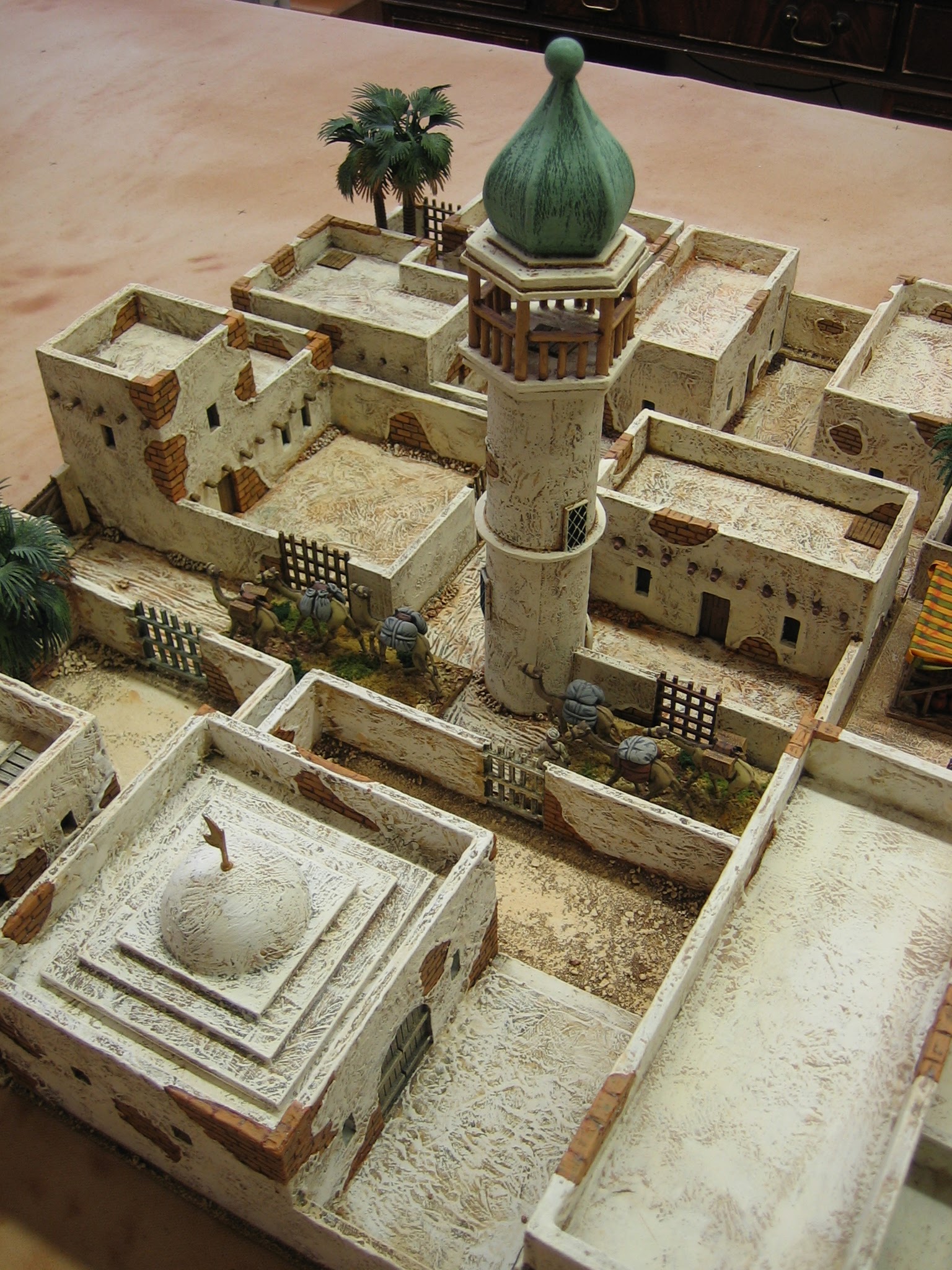
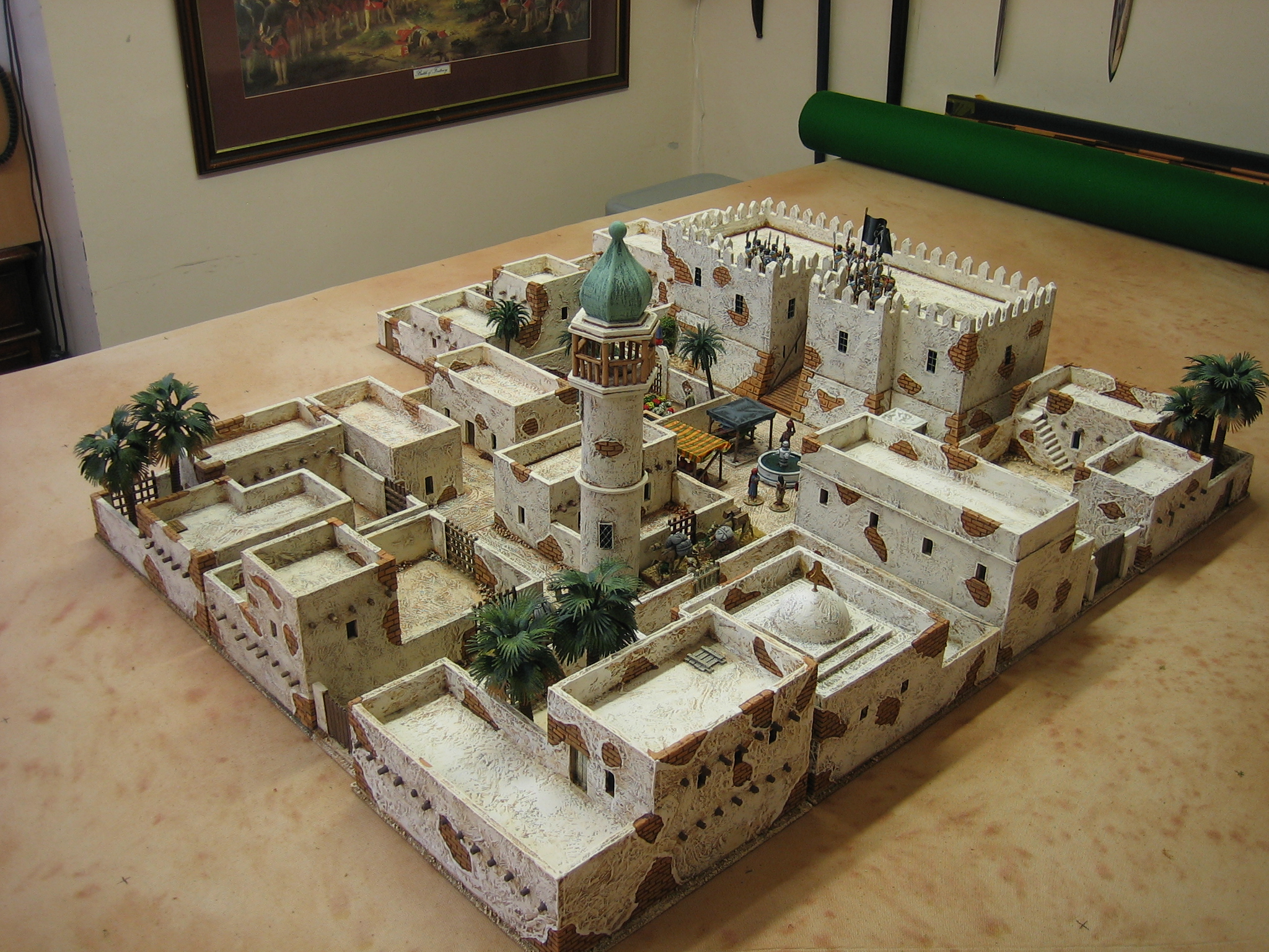
My Middle Eastern building collection has grown over the years. Originally designed as generic buildings for use with my Crusades collection it will now also serve for my colonial adventures in the Sudan. 

Funnily enough, I have little idea of what buildings looked like in the Holy Land in the 12th century and I've only seen a few images of Victorian era buildings in the Sudan. However, these buildings somehow look right for both, even if they are probably not: I put this down to most Middle Eastern wargame buildings looking like this (flat roof with parapet) and this familiarity has, as is often the case, bred a contempt for anything more 'historically accurate'.

Each 'town section' is on a 21cm square base. They would be better on 20cm square bases, to go with my To The Strongest rules table grid, but that did not allow enough room to build enough space to house my troops - each has a capacity of two units. Some of the sections have been designed with attached streets to make a workable road network. Most of the sections have buildings in a self contained compound - a feature common in the Middle East. This compound design allows for my town to be fully enclosed, without the need of separate town walls, and accessible only at town gates; the town gates are separate features that can be removed. So far, I have 14 town sections.

The largest building is the Emir's Palace. Effectively, it is two sections; it serves as the town's / governor's 'citadel' with a reasonable table footprint.

Unlike most of my buildings this one has moving parts - the drawbridge works!
A very simple town section is the market. This is simply a textured base with movable stalls and fountain. Effectively, it is also a very useful 'crossroads' connector piece.
To look after the spiritual side of town life there is a small mosque and minaret. 

The dome and stepped platform on the mosque roof can be removed for the deployment of troops. It has a central locator pin to keep it in position.

At some point I'm going to make a bigger mosque.
Another simple town section, with a bit of difference about it, is this ornamental garden. The shrubbery is made out of Woodland Scenic clumps - the low hedging has been flocked, the flowers are painted clumps. Everything is at more or less the same low level so that troops can be placed on top.
Some sections are usable in more than one way. This one, with a central road 'T' junction, has a moveable wall to enclose the piece when on the outside of the town...
When on the inside the central road can lead to a compounds centrally located gate.
Most of the buildings are simple one or two story affairs and often mixed on a base to make the whole look a bit 'jumbled'.
The amount of broken plaster, showing underlying brick work, came about after reading of the decrepit state of the villages in the 12th century Holy Land following steady depopulation over the previous four centuries: it seems that there simply wasn't enough manpower to repair anything! 

The palm trees are not fixed but, they add to the hot dry feel of the place.
Another shot. The town is 84cm wide and 84cm deep at it's widest points.
All of the buildings were scratch made using 5mm foam board, 2mm MDF (especially the bases), and card (mounting and old postcards, the latter used to make the brickwork). Doors, trapdoors and main gates are balsa. Grilled gates are plastic (cut up plastic bases by Perry).

Plasterwork is mostly artist's (tubed) heavy body acrylic. 

Any framed windows, and a couple of the doors, are by Warbases.
I'm quite happy with the town but, it needs two more sections so that the whole thing can be made square (16 sections), plus another two or three sections for outlying farm / village compounds.


Wednesday, 12 April 2023

Mid War Spanish Additions (cont.3) - Toledo

Two battalions of Regimiento de Toledo in the uniform dated to 1811-13. I liked this uniform so much that I wanted to paint up two units in it rather than one. I think you'll agree that it is a belting combination of colours.

Now, caveat emptor, there is a fudge with these figures: The modern plates I have of the uniform all show tight pantaloons with short gaiters over the top (possibly all copied from the same original source). My figures are wearing trousers because it would be to much work (and possibly beyond my skill level) to file down all of those lower legs to make their trousers look like tight pantaloons with gaiters over the top. However, I'm not the only gamer who has this regiment in trousers: JJ has some too and you can see them on his excellent blog, here. Believe me, if it's close enough for JJ, it's close enough for me!


Although a bit blurry, this photo shows the two extra stands of skirmishers that come with each unit, making each unit 28 figures strong. 

All are based on MDF stands, 45mm square and round, 2mm thick. Round bases by Warbases

Both Toledo flags are by Adolfo Ramos.

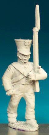
Here is the thing though. Most of these figures had to be converted because Front Rank don't make this figure with shoulder straps, let alone tufted shoulder straps, or a pompom. Furthermore, the casting comes in a simple coatee without lapels.

This how they come from Front Rank (randomly one with moustache, one without).

The conversion: 

First I removed the row of buttons that ran centrally up the front of the coatee with a scalpel. Lapels and new buttons could be painted on later without further modelling.

The pompoms were made out of modelling putty (Milliput). I found the best way to get them all the same size was to roll out the putty into a thread about 2mm thick and cut it into small (equally long) lengths - I did this by eye and it worked pretty well. I rolled each length into a ball between thumb and forefinger before dropping them onto a tile to cure. When they were hard, I glued them to the top of the shako with a two part epoxy glue (Araldite). I put a small dab of this at the front of the shako with a large pin (a wire spear) and then placed the pompom on top with tweezers: The glue is viscous enough to hold the pompom in place until the glue cures. Initially I had sought to use superglue for this job but, this was really fiddly and the balls stuck to the tweezers more often than the shako - I soon gave up and went with the Araldite instead.

The real work came doing the tufted shoulder straps. I did the figures in small batches (about six figures each) because the whole process needs to be done using soft modelling putty (Milliput). First I rolled out a thin thread, perhaps slightly more than 1mm in diameter and cut it into lengths that were a little longer than I wanted the strap to be. I placed the thread of putty in position on the shoulder then flattened it onto the figure with the flat of a wet scalpel blade; then, using the scalpel, I trimmed it to the correct size and shape - note that you need to leave room for the tuft. Next, using a a length of putty thread that was the thickness I wanted the tuft to be, I placed short lengths crosswise at the end of each strap lightly pressing the two together so that they lightly stuck, then I trimmed the tuft at either end to the right length. When cured, I put a bead of superglue onto a tin lid and, using a pin to pick up a small amount, traced the glue under the tuft where it met the shoulder to secure it more firmly.

Following this, before undercoating, I painted the straps and tufts by hand using some gloss enamel paint to bind the lot together even further - gloss paint is almost as good as glue and you can get a consistent coat over the lot to seal everything in. Belt and braces every time!
 
Then it was just a matter of painting them. 

I really like everything about these boys and it was a pleasure doing them. Brown wouldn't be every one's choice of coat colour but in combination with the other colours I think it looks splendid.
So there we have it. two battalions of Regimiento de Toledo.

Next up, Regimento de Leales de Fernando VII in their uniform of 1810.


Thursday, 25 November 2021

Bulking out a command stand: A roadside shrine


I'm in the process of sorting out the last batches of figures to finish the Anglo-Portuguese and French armies. 

I had always planned to do a second corps command stand for the French (because I can see two corps commanders featuring at the same time) and consequently, I've had three mounted figures and a couple of foot figures to do this in my lead pile for a long time. 

I hadn't planned anything similar for the Anglo-Portuguese but I had thought about having a Beresford command stand (I even painted him). Then I decided he was surplus to requirements and didn't rebase him when I rebased the other officers.  

However, whilst rummaging through the bag of odds and sods (left over from the project) I came across another unused British mounted officer. That would be two mounted figures, and I have an unused painted foot officer and an unpainted sergeant marching with his partisan over his shoulder: But, that is still not quite enough for a full C-in-C stand. Could I use a 'stand filler' as the extra piece I would need?

I could make a signpost as a filler, or a blasted tree trunk, or what about a roadside shrine! A shrine would not be out of place in a very Catholic Spain.

A roadside shrine could be quite big, at least as big as a figure, and it would be more eye catching than a signpost, or a tree stump. 

I'm not a great model maker, average at best, but even I could probably manage a cross in some kind of housing, perhaps on a Milliput stone plinth with a kneeling step. 

I had some bits of plastic (Perry plastic bases and Airfix bits) I could cut up to make the cross and the housing, and Milliput is always to hand, so I got to work.

Then I decided that a proper crucifix might look better - more eye catching - than a plain cross. Sculpting is something I'm not very good at at all but, the Christ figure would be tiny and being such a recognisable thing only an impression would be needed. Out came the Milliput and in a jiffy I had this little piece of treasure - it's not that good but, you immediately know what it is.

I'm not sure how I'll paint the crucifix. Perhaps as a brass Christ on a wooden cross, or perhaps all wood, or all brass. Not being all that up on early 19th Century Spanish shrines I'm open to suggestions.

BTW, the plinth isn't a solid lump of Milliput. It's actually a block of balsawood with a coat of Millitput applied to the outside. Other construction is all visible. 


Edit: I have painted it up with a carved wood crucifix (which I could always, and simply, repaint as brass) and I think it looks pretty good. 

Here is a close up of the Christ. You can see just how simple I made the construction, with rolled Milliput for arms and legs - position, more than detail, being everything.


Thursday, 28 October 2021

Humpback bridges, cheap and cheerful.


Having made about seventeen feet of stream some time ago I needed some bridges. I decided on three. They needed to be small, so simple humpbacked bridges seemed the best route. I chose to go simple. I chose to go cheap. I chose to play a trick. Then I built them, fell ill and didn't post this as originally intended - fortunately I remembered to take the memory card out of my camera so that I didn't accidentally erase the pictures; erasing pictures on the camera card is something I do regularly to speed up the find and download process.

You don't need many materials or tools to make these things, and those materials you will need are useful for many other things - so no pointlessly wasted materials left over. Cheap as chips - £0.50 each, tops.


Biggest cost can be seen here, 5mm foam board. But, it has so many uses that you'll use what you don't use on this job for others - zero waste here.

Having marked out the sides of the bridge using a set square, ruler and a compass onto 5mm foam board I cut the shapes out using a surgical scalpel with a 10A blade. 

Note that the bridge was deeper than this when it was drawn: It's had about 5mm cut off the bottom; that's where the compass point at the centre of the circles was located. The arch isn't quite a whole semicircle.

My stubby handled size 10 scalpel is probably the most used tool I own - I use it for just about everything because the blades are much cheaper than craft blades, and if you mutter to yourself whilst you work, it's funny to say "Scalpel, nurse." once in a while.

If you are watching carefully you will have noticed the trick I'm about to pull already. Can you see it yet?


Edit for RichardL: Easier said than done now they are made but, approx dimensions are: Length 120mm. Height 40mm. The lower arch at waterline is 40mm across. The arch corresponds to the width of my stream and it is that wide for no other reason. Just do what feels right for the water you want to cross. If the river is much wider you may need two or more arches like this one I made some time ago.


I didn't throw away the angles from the top of the bridge walls as these will be used....
...to make the ramps that will support the roadway. 

The trick is obvious now, isn't it?
Whilst the roadway support ramps were drying, I cut out my 2mm MDF bases to match my stream basing. 

This is another outlay similar to the foam board but, again MDF is such a useful thing to have around the place.

BTW: To buy quite small pieces of 2mm MDF look up picture framing supplies - it's used for backing pictures.
I cut the excess off from the road ramps and now the basic structural work is done.

Got the conceit I'm planning. Surely you see the trick now?
I added my stream texture, and two strips of foam board to the basing. These foam board pieces will stiffen the bottom of the lower arch and keep its sides straight at water level. (See second picture down: That picture shows how these strips work).

You can see that I do my footprint plans bold, using a fine felt tipped pen. The "52mm" is to remind me how wide to cut my roadway. 

Also note that before I did the water texture I masked off the areas where the bridge will sit. This needs to be flat.


The lower arches, made from thin card. I actually used cartridge paper in this case but, anything from old Christmas cards to cornflake packet is about right. 

The pins just hold everything in place whilst the glue dries.
Now here is the big fudge: The conceit that makes these bridges work. 

The problem with wargame bridges is that they usually have to go over water that is above ground level. Obviously, 'in the wild' streams flow a few feet below the level of the surrounding ground. This means that the arches of a wargame bridge, to look right as arches, actually have to be higher above ground level than they should be. This causes a problem for the modeller. Either he has to have bridges with an incredibly steep roadway or he has to make bridges overly long to make the road gradient less steep.

I have done neither. My conceit is to lay the roadway directly over the lower arch, thus reducing the overall height of the roadway by 6mm - 7mm. Thus, the bridge can be short and the road gradient shallow. But, the level of the road is lower than the stone arch on the outer wall of the bridge that is supposed to support it. That's the trick! The eye will be tricked by not being able to see both the outer arch and the roadway at the same time. It's so simple, it's downright stupid.

Because I was using cartridge paper I did my roadway three layers thick, one applied after the other. If I had used Christmas cards, two layers would have sufficed. The last layer went over the base edge and was trimmed flush when dry - only do this with the last layer; cut the other layers shorter, as in the picture above.

After doing the brickwork using thin balsa wood (bricks and arch-work) or mounting card (top stones on the walls), and texturing it and painting it with household acrylics (Dulux emulsion paint), I coated the roadway with a strong mix of plaster filler and PVA / water (1:1).
I painted the road, adding a few rocks and some 'verge' to the inner surfaces, and based and painted the stream to blend into my streams.
Here the conceit of the roadway is explained. The eye doesn't see the relative heights of the arch and the road because it can't see where they join. It is tricked completely.

One last point. Most humpbacked bridges have a splayed entrance, the roadway being wider at the entrance to the bridge and narrower in the middle. This is actually very difficult to do and causes problems when it comes to cutting the shape of the roadway. To make things simple for myself, I chose to ignore this facet of a humpbacked bridge completely: K.I.S.S.